
A tutorial on how to do some simple in-place linking with 3D printing.
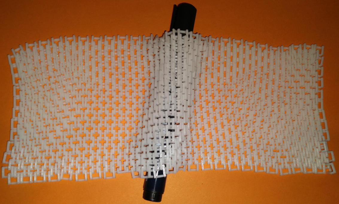
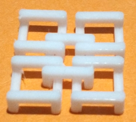
One of the more surprising feats of 3D printing is to create in-place links. Above you see a piece of printed "chainmail" that does not need any after-the-fact assembly or gluing.
I'll be showing this example using FreeCAD and OpenSCAD. The principles will be similar using other 3D design tools.
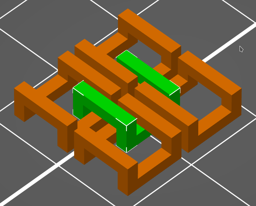
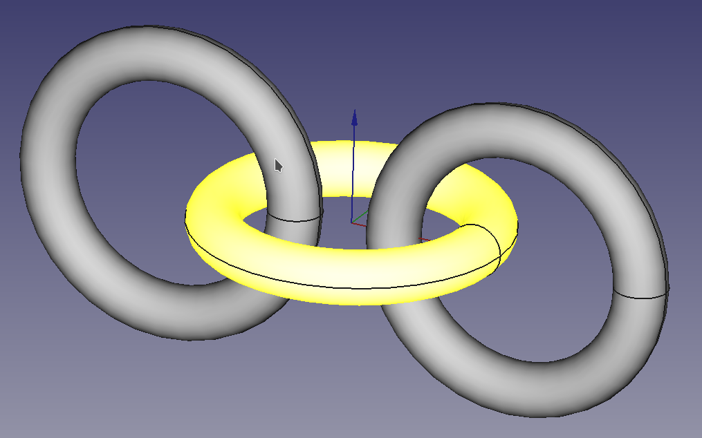
Intuitively you imagine something like the three linked rings on the left. This of course will not work, since it would require the printer to create bodies that float in the air without any support. Instead you need something like the chain links shown on the right.
The important trick is to give each body enough support from the printing surface, while also using clever overhangs to bridge those supports and gaps to separate the bodies from each other. The result should be something like the linked elements on the right. But to arrive at this we need to talk about overhangs first.
An overhang is a feature that has no support material directly underneath it. A feature above an overhang does not count as a support, since it will not be there when the overhang itself is being printed. There are several types of overhangs. An overhang can be supported on one side or both sides. It can come out of a vertical wall at a right angle or it can be part of a gradual slope at an angle.
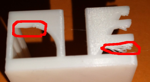
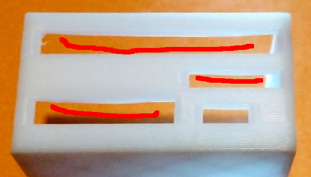
An overhang that is supported on both sides behaves similar to a clothesline while being printed - it droops a bit while being strung between the two walls. The longer the overhang is, the more pronounced the droop becomes. You ca see this in the right picture above: the smallest hole is 5mm wide, the one above it 10mm, bottom left hole is 15mm and the top hole is over 20mm wide. On the top hole you can see that some strings droop quite a bit, while on the smallest hole practically no drooping is visible. The exact length at which an overhang becomes problematic depends on many factors: the material that you use, its quality, the temperature at which you print, how fast the print head is moving, and how good the cooling fan works. The only way to find the limits of your particular setup is to experiment. As a general rule: 5mm will usually be fine, 10mm will often be getting close to the limits.
Overhangs that are only supported on one side are far more fragile, since there is nothing to stop the string of plastic to just give into gravity on the unsupported side. Anything above 1mm will usually give you quite ugly fraying - as seen on the right side of the left picture.
If you print vertical curves, slants or diagonal features the problems depend on angle. The angle that will yield problems is again dependent on material, printer and print settings and can only be determined experimentally. In the picture on the left you see one such experiment with problems appearing at the top. Usually an angle up to 45 degrees will be fine.
Under normal circumstances you can compensate for these problems by letting you slicer create support structures - less solidly printed features within the open spaces that support the overhangs during printing and are removed after printing. For in-place linked prints this is normally not an option, since the additional supports would weld the parts together and be almost impossible to remove because they are hidden in hard to reach spaces. Thus we have to limit ourselves to overhangs that don't produce big problems yet.
For this example we use an extremely simple design: we form the individual chain links from a simple cube and carve out spaces, so that the result rests on "skid" like structures in the X-direction and the overhangs that cross-link them together are in the Y-direction. All links are identical and arranged so that the overhangs of each link traps the skids of the two neighboring links and conversely the "skids" of each link trap the overhangs from below. With this arrangement the links form topological knots around each other and can no longer be separated (except with a wire cutter).
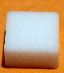
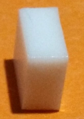
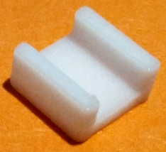
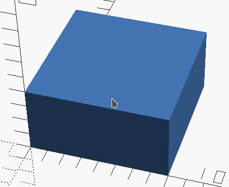
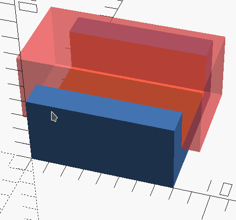
In the design process we start with a simple block (see above). Into this block we carve a channel that leaves two skids at the side and enough material to keep it all together (see below).
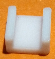
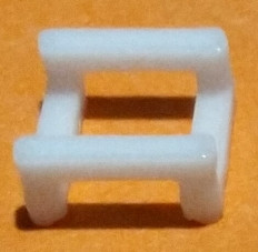
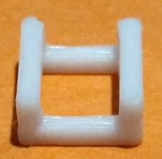
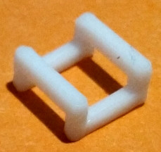
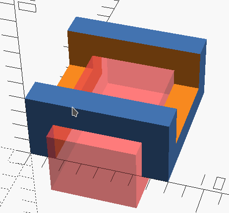
Then we carve a similar channel on the other side, but in a perpendicular direction (see below). The two channels should overlap vertically, so that a hole is formed that is big enough to fit the corners of four other links. This leaves us with the structure we need.
If this is printed together (or cut and glued) then we get the full result below. You can see how the middle link weaves through the gaps of the outer four and with that links them together.
The same principle can be used in arbitrarily complex in-place links - every part needs some support from the print bed and then uses an overhang between those supports to weave itself into or above another part.
For the mathematically inclined it is often easier to construct these parts in OpenSCAD by using a geometric description and algebra to arrive at a complex shape. If this is not your style - skip ahead to the FreeCAD section below.
Stage 1: we define a cube. In this example we use a cube that is 8mm wide and 4mm high - the final features are supposed to be 1.5mm wide - this gives us an inner hole of 5mm and plenty of space to place the structures of linked parts.
//    x  y  z
cube([8, 8, 4]);
Stage 2: we need to cut the first channel. In OpenSCAD this is usually done by subtracting another body from the base - the command to do this is difference() (below in red) - it takes the positive base as first parameter and every subsequent body is subtracted from it. The first channel is highlighted in blue in the script and as a pink translucent body in the image below. The translate() command moves the body to the right position to form the channel. You will notice that it is bigger than the channel - OpenSCAD has problems understanding the concept of "zero width" - it would create an ultra-thin "skin" at the interface of the two bodies. By making the subtracted body bigger than it needs to be we make sure that OpenSCAD understands what we want to take away.
difference(){
    //    x  y  z
    cube([8, 8, 4]);
    //          x  y    z   -->     x   y  z
    translate([-1, 1.5, 1.5]) cube([10, 5, 4]);
}
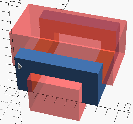
Stage 3: next we cut the second, perpendicular, channel. It is again highlighted in blue (script) and pink (image) below.
difference(){
    //    x  y  z
    cube([8, 8, 4]);
    //          x     y     z    -->     x   y  z
    translate([-1,    1.5,  1.5]) cube([10,  5, 4]);
    translate([ 1.5, -1,   -1.5]) cube([ 5, 10, 4]);
}
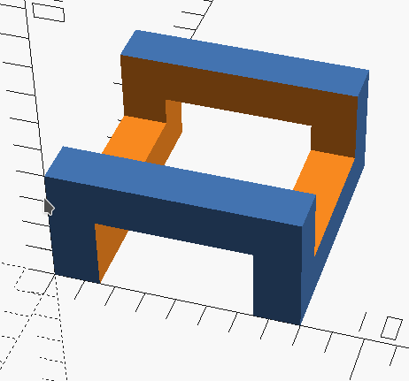
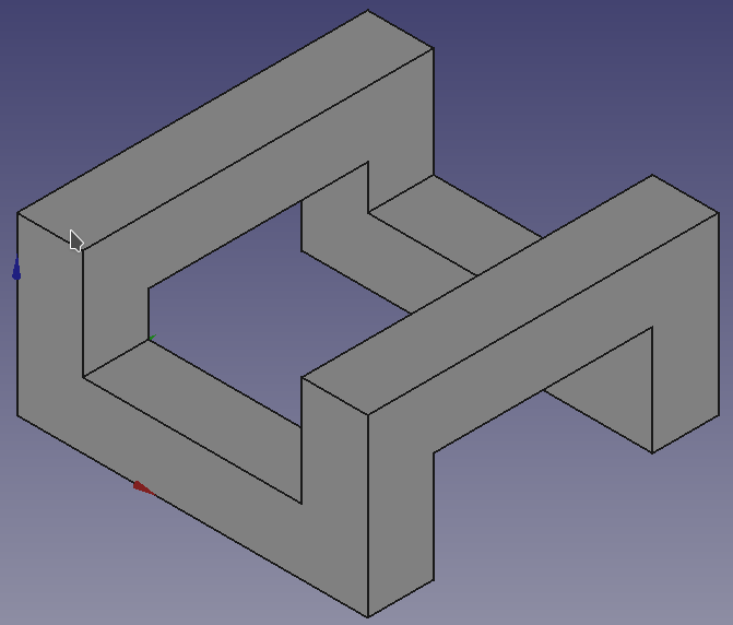
Result: below you can see the final body with both channels highlighted on the left and without highlights on the right.
To make this available to the slicer press F6 to render the body properly and use the "File" - "Export" - "Export as STL" menu to generate a STL file.
Go to the Slicing section to find out how to place the parts for printing.
In this example we use a cube as basis that is 8mm wide and 4mm high - the final features are supposed to be 1.5mm wide - this gives us an inner hole of 5mm and plenty of space to place the structures of linked parts.
To construct the link body we use the "Part Design"  workbench. First we create a new body
  and then a new Sketch
  inside this body.
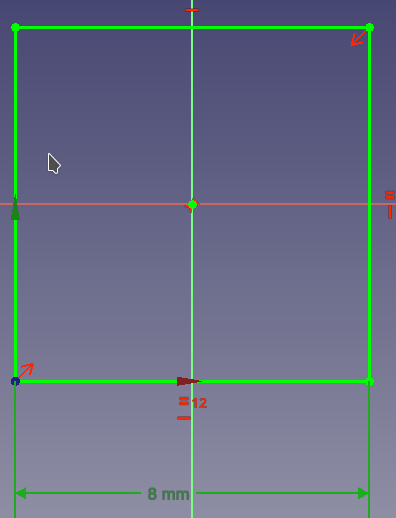
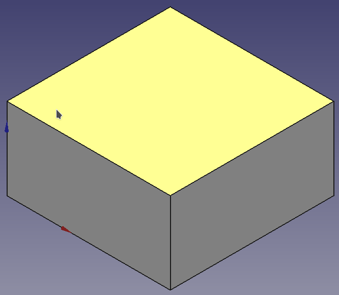
First we create the solid cube. We bind the sketch to the XY-plane and create a simple square  of size 8mm × 8mm (above left). The we extrude the square into a Pad
  (above right). Set the pad height to 4mm.
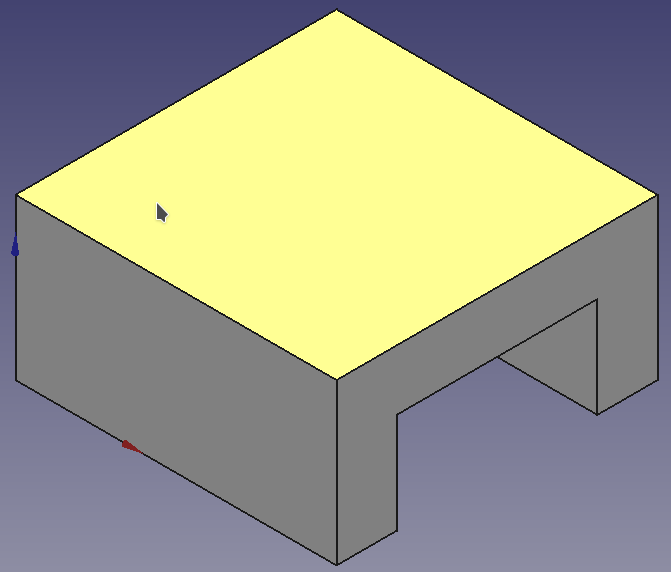
Second select the top face of the cube (yellow above) and create a new sketch on it.
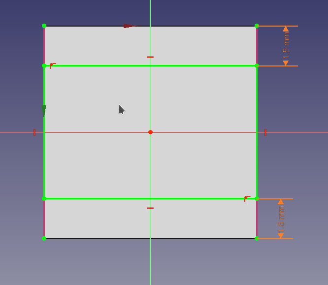
Get the sides of the existing cube by using the External Geometry  tool and clicking the side lines. Bind a rectangle
  to those lines and constrain the distance
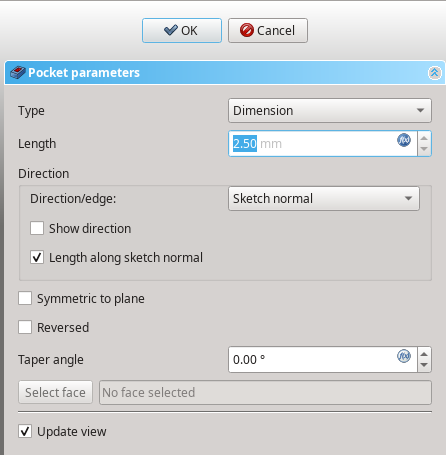
  to the top and bottom to 1.5mm. Exit the sketcher and create the channel by turning the sketch into a Pocket
  of 2.5mm depth.
The last step is similar to the second one. This time we select the bottom face (yellow above) of the cube and create a new sketch on it.
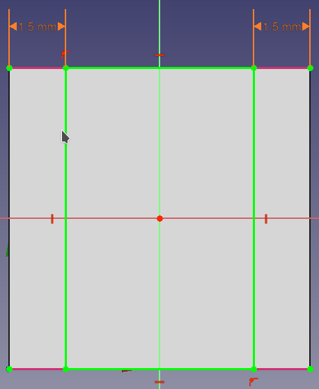
This time the channel needs to be oriented perpendicular to the first channel, so we select the top and bottom lines with the External Geometry tool and constrain the distance to the left and right to 1.5mm. After exiting the sketch we again turn this sketch into a Pocket of 2.5mm depth.
With this we can export the body to an STL file: click the body in the model tree and go to the "File" - "Export" menu to save it as STL.
After that we continue with the slicer below.
Open your slicer program and load the STL that you exported from OpenSCAD or FreeCAD. This is just a single link, tell the slicer to create multiple instances of this part. Use the mouse to arrange those instances in the X- and Y-direction so that they are interlinked:
Make sure that the links do not overlap and have a bit of space between their features - 0.5mm is enough, but it should not be below the with of your print features in order to avoid accidental fusion of those links.
Click "Slice Now" (or whatever button your slicer provides for this function). If your slicer allows you to iterate through layers it will look something like this (animated GIF):
You can see how the print begins by laying out the "skids" of those links next to each other with some interleaving. And then on a higher layer the parts get bridged by creating those overhangs (the first overhang layer appears in blue in this animation).
On my Prusa MK4 this print takes about 4 minutes.
The chain mail sheet pictured at the top of this page was made by linking about 600 identical parts and took about 5 hours to print.