
A tutorial on how to use FreeCAD for simple 3D print designs.
...who doesn't want to munch on a low calorie lollipop all day without the risk of actually enjoying it!?
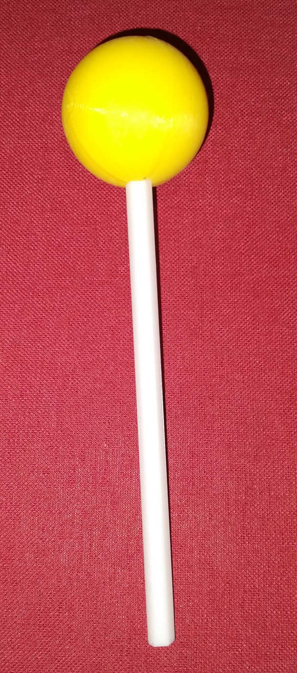
This was simply an experiment in prop-making - I wanted a lollipop that looks realistic, but is not a problem for continuity - i.e. it is never used up.
(Side note: I'm not actually a film guy, I just admire their craft.)
Everything about this lollipop is 3D printed. This creates a few limitations. It can't just be free standing while printing. Different colors have to be printed separately (on most printers). I'll describe the details below.
You can download the final FreeCAD file here: lolli.FCStd
I utilized the "Part Design" workbench in FreeCAD 0.21 (stable version as of writing this).
PLA is okay as a 3D printing material for this - there are no stability requirements. PLA is also usually food safe, so it could be used by an actor to pretend licking it. You need a bright color for the ball - preferably something that looks like it could be a real lollipop. The stick should be a pale color - white, wood, pale yellow, or pale brown. Dark or bright colors would look fake. To assemble it all you need a few drops of cyano-acrylate glue (super glue, gorilla glue) - it works well with PLA and is usually non-toxic once it has cured.
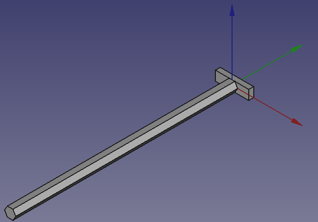
Lets start with the stick: I'm using a simple hexagonal profile - this is a compromise between the round stick you'd normally see in normal lollipops and a square profile that would be easiest to print. The hexagonal profile becomes only visible in close-up photography and still looks plausible. The stick has an additional blade on top - this is hidden from view when the lollipop is assembled and serves as an alignment aide during assembly.
Select the "Part Design" workbench - we will be using this one for the entire design. Create a new body  and a new sketch
  inside the body. I attached this sketch to the XZ-plane (one of the verticals) because it represents the edge of the stick and we will be printing it laying flat. This makes it easier later on during printing.
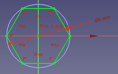
We start by creating a sketch of a 5mm diameter hexagon  - anchor the center to the origin point, by clicking there for the first point. Link the second point to the horizontal axis by clicking the axis second and assign a diameter
  constraint. Now the entire sketch should be green and FreeCAD should show that it is fully constrained. This means that it is no longer possible for the sketch to move around and produce a 3D object that we did not intend.
Close the sketch and extrude (pad)  the sketch 100mm - this seems to be a nice length for most hands.
Select one of the hexagonal faces of the stick and put a sketch on it. For convenience I chose the face at the origin point - it makes aligning the ball easier. Use the "external geometry" tool  to capture one of the horizontal lines of the hexagon - you'll need it for making the blade the same height as the hexagon. Add a rectangle
  that centers on the origin - just like we did with the hexagon. Use the "contain point onto object" constraint
  to attach one of the horizontal lines of the rectangle to one of the ends of the external hexagon line.
If the rectangle missed the origin point while you were drawing it, you can constrain it explicitly by adding a  point-on-point constraint and clicking the center point of the rectangle and the origin point of the sketch.
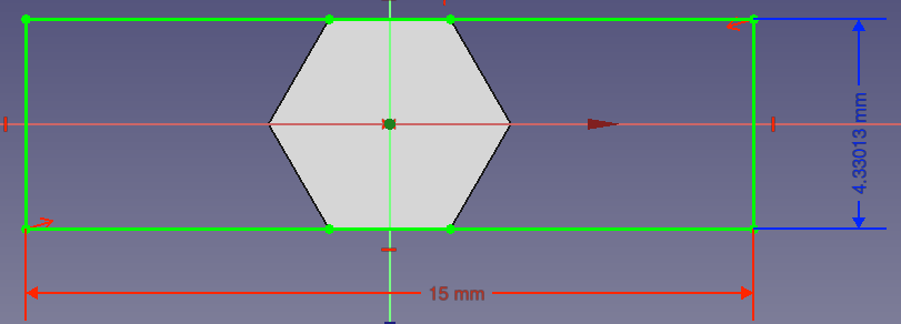
Now you only need to constrain the width of the rectangle: give it a sensible width  that is easily hidden inside the ball. The sketch should already be fully constrained. But we'll need a couple of references for later when we carve out the inside of the ball: give the horizontal length a name. Attach a vertical length
  constraint to the vertical edge of the rectangle, but mark it as a "reference" - this allows you to measure an already constrained length. Also give this reference a name.
We turn the rectangle into a pad - about 2mm gives us a very stable printed wall. We will need to align this extrusion length with the corresponding hole in the lollipop ball, but unfortunately it cannot be named and referenced. We'll solve this conundrum below.
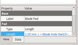
Pro Tip: in the Property Data table of each sketch, pad and other feature you can set a "Label" - this is displayed as the name of the feature in the FreeCAD hierarchy and also becomes available in references. I recommend to use these labels to give yourself a hint what the feature really means - this reduces the time to search for a specific feature for changes and also makes referencing sketches elsewhere much easier.
Next we'll be designing the extremely low-sugar ball (unless you have access to edible filament). Most FDM 3D printers will have trouble printing a ball shape in one go - either you'll need to add support structures, which are never as easy to remove as advertised, or you will end up with some pretty ugly sagging and possibly a detached print. To avoid those problems we simply split the ball into two identical halves. While those halves will have some hang-overs they are small enough not pose a significant problem.
Create a new body for one half of the ball. We'll start with a sketch on the XY-plane (horizontal). A half sphere can be created by rotating a half circle 180° around its straight edge. Let's do this: create an arc (with center and end points) - center it on the origin point of the sketch and attach the two end points to one of the axes. Give it a diameter that is a decent sized lollipop in your opinion (through experimentation I found 28mm most convincing for myself). Now connect the two end points of the arc with a straight line. You may have to delete a redundant constraint if FreeCAD auto-constrains the line to be horizontal or vertical. FreeCAD will tell you which one offends the internal constraint Solver.
Pro Tip: you can make a body invisible and visible again by selecting it and then tapping the space bar on your keyboard or by right-clicking it and selecting "Toggle visibility..." from the context menu. This helps with overlayed sketches if a 3D shape is in the way of editing.
Close the sketch and turn it into a "Revolution"  of 180°. You should end up with a half sphere.
Now it needs to be mounted on the stick. This means we need to carve out a hole for it. One of the things we need to consider here is tolerances or how much play we give the stick inside the hole. Even the most modern 3D printer are not perfect - if we print matching parts without tolerances, chances are they will not fit. The hole will be slightly too tight or the feature going into a hole will be slightly too thick. My own printer makes a layer height of 0.2mm and a track width of 0.4mm - tolerances should generall be in the same ball park as these properties, so I usually chose tolerances of 0.2mm to 0.5mm. Unless there are other considerations that require or allow even greater tolerances.
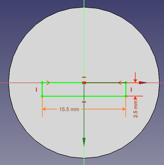
Select the flat surface of the half sphere and add a sketch to it. It would be difficult to teach FreeCAD to carve out part of a hexagon from this side, so we delay this a little bit and carve out the alignment blade first. Let's attach it to the center of the ball - we create a (non-centered) rectangle  , then we need to center the top line of the rectangle to the center of the ball. This can be done by constraining to a symmetry
  - select the symmetry constrant, click either the top line or the two outer points of that line first and then click the origin/center point of the ball. FreeCAD will align the line so that it is always centered on the origin point.
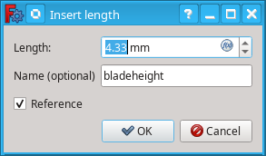
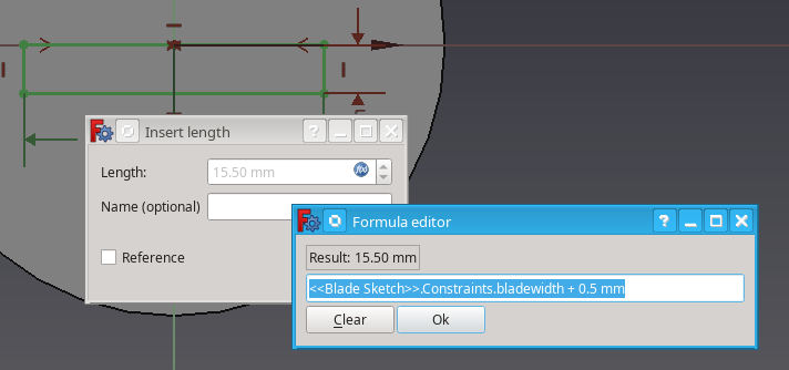
Next we need to constrain the width and height of the rectangle. The width can be calculated from the width of the original alignment blade at the top of the stick. We use an Expression for this. First check what the label for the original blade sketch is - in my version it is named "Blade Sketch". Create a horizontal length constraint and click the expression  button - a new dialog opens and you can enter a formula. Start entering the name of your original blade sketch and FreeCAD will offer candidates, select the correct one. We want to reference a constraint from that sketch, so we add ".Constraints." (FreeCAD offers auto-completion again), and add the name of the width constraint. Now we only need to add our tolerance, for example "+ 0.5mm". See the image below.
The height of this rectangle and the thickness (length) of the blade pad are related, but unfortunately we cannot name the length in a pad. So we simply reverse the relationship: give the rectangle a sensible height - like 2.5mm and give this constraint a name that we can reference from the pad (e.g. "bladeholedepth"). Now the sketch should be fully constrained and we can close it. Turn it into a Pocket  . In the pocket dialog click the expression button to make it automatically related to the actual blade. Since this is half of the ball, the pocket should fit half of the height of the blade plus a tolerance. For example: <<Blade Sketch>>.Constraints.bladeheight / 2 + 0.5mm .
Now that we know how to use an expression, we can correct the original blade pad - open it by double clicking and enter a formula that references the pocket sketch. For example: <<Blade Hole Sketch>>.Constraints.bladeholedepth - 0.3mm .
Side note: make sure to not create circular references - those will confuse the Solver and lead to errors.
Now that we have a pocket with a wall that goes into the ball we can attach a sketch to this wall and use it to carve out a gap for the hexagonal stick. Zoom in on the pocket and select that wall (see above), then attach a sketch to it. Of course the half sphere is in the way for drawing, so you need to make it invisible (see Pro Tip above; you may need to close the sketch, make the body invisible and then re-open the sketch). Like in the first sketch we did above: create a hexagon centered on the origin point and linked to the horizontal axis. Give the hexagon a diameter slightly larger than the stick's - the best way is to use an expression again. E.g. <<Stick Profile Sketch>>.Constraints.stickdia + 0.5mm .
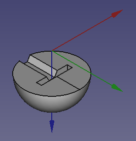
Create a pocket from the sketch and make it at least a few mm deeper than the radius of the ball to make sure it goes all the way through. The half ball should now look like the image at the start.
This is already everything that is needed to prepare for a 3D print. If you did all the alignments correctly you can simply make both bodies visible and check that the stick fits into the half ball.
If you like you can use the properties (under "Placement" in the property Data table) of the bodies to move them around on your screen so that they look nice when opening the file. For the file linked at the top I even went so far as to create a clone  and using the placement properties to rotate it so it looks like an "exploded view" of the entire lollipop. The nice thing about a clone is that it will always stay identical to its template if you make changes.
To print those parts you need to export them to your printer. There are various tutorials online, some of them use a rather scenic route through meshes and other adventures. For my own purposes I find it easiest to simply export to STL or STEP and then use the printer's slicer to do the printer specific part. Simply select the body you want to export and then click the "File" menu and "Export..." (or use Ctrl-E).
The STL format is a simple 3D mesh that is understood by pretty much all slicer programs. It represents the body as a mesh of triangles, but that means that it loses precision at some scaling factor. For FDM printing this is usually not a problem, since the precision and feature size of the print is much less fine than the meshes usually generated by FreeCAD. STL is the normal exchange format for most 3D printing.
The STEP format was designed as an exchange format between CAD systems and as such renders much more precise than STL. However, it is also a lot more complex and not all slicers understand all features in all STEP files. STEP is able to handle designs that use Parts  to assemble multiple bodies into a complex part, but for simple bodies STL is usually preferable as a printable file.
Simply export both the stick and the half ball as an STL and then open them in your favorite slicer (Slic3r, Cura, Prusa Slicer, ...) - the stick should lay flat on the print bed and the ball should be oriented with the flat surface towards the bed. You will need one stick and two half balls. While it is a good idea to print both half balls at the same time, the stick should be printed separately with a different color - depending on your printer color changes can be quite costly and inefficient. Some slicers will ask you to print supports, but this should normally not be necessary - the only real overhang is only a few millimeters wide - if your printer has a problem with that then it will benefit from some calibration and temperature tuning.
Once the prints are finished you can simply assemble the lollipop by dabbing a few drops of super glue onto the half balls and the blade at the top of the stick and then just press them together. You only need a few drops, otherwise the glue will squeeze out at the sides. Since the main surfaces are rather large compared to the total part size not much glue is needed.
Pro Tip: wait a few hours before you lick the lollipop or give it to anybody else! Wet super glue would attach your tongue to the plastic faster than you can move it away.
Hint: super glue cures by reacting with the humidity in the air. Tongues are very humid. Use caution and common sense.