
The idea for this utility is to have a very simple template and ruler for your awl while punching holes into signatures for easy binding.
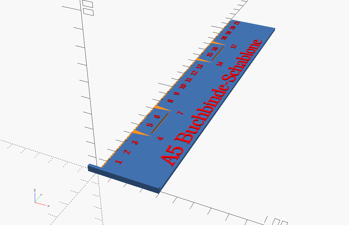
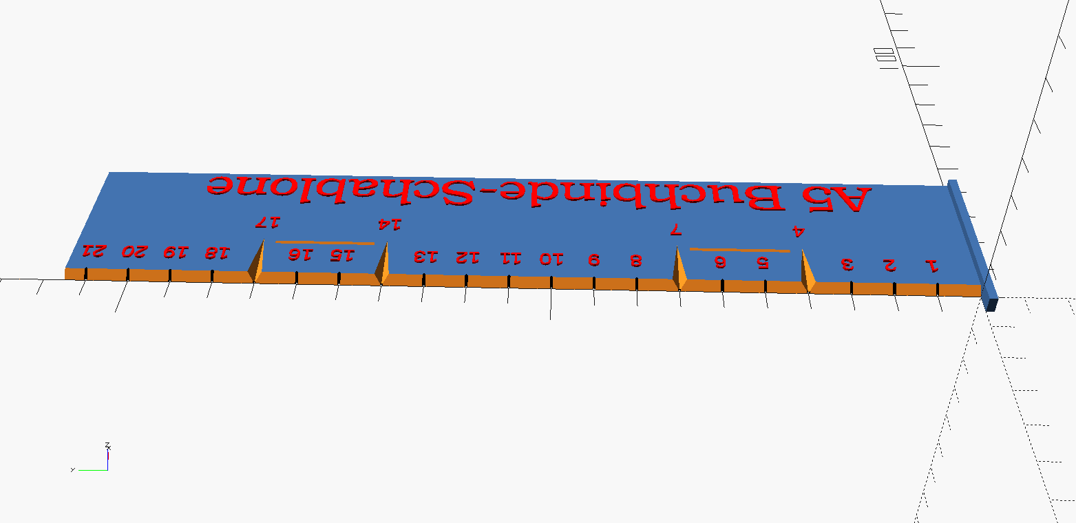
It is optimized for printing on A4 - two pages per side - and then folding to A5. The resulting fold is 21cm high. There are hole markers for two rows of stitches, each 3cm wide, at a position that is far enough inside for pretty much all edge trimming needs at that format and far enough apart to impart good stability.
The ruler will still work with US letter or legal paper as the base stock, since the fold would only be about 6mm longer. This should not be a problem, since the stitches are mostly hidden in the finished book and you will usually cut a much bigger margin when you trim the book block.
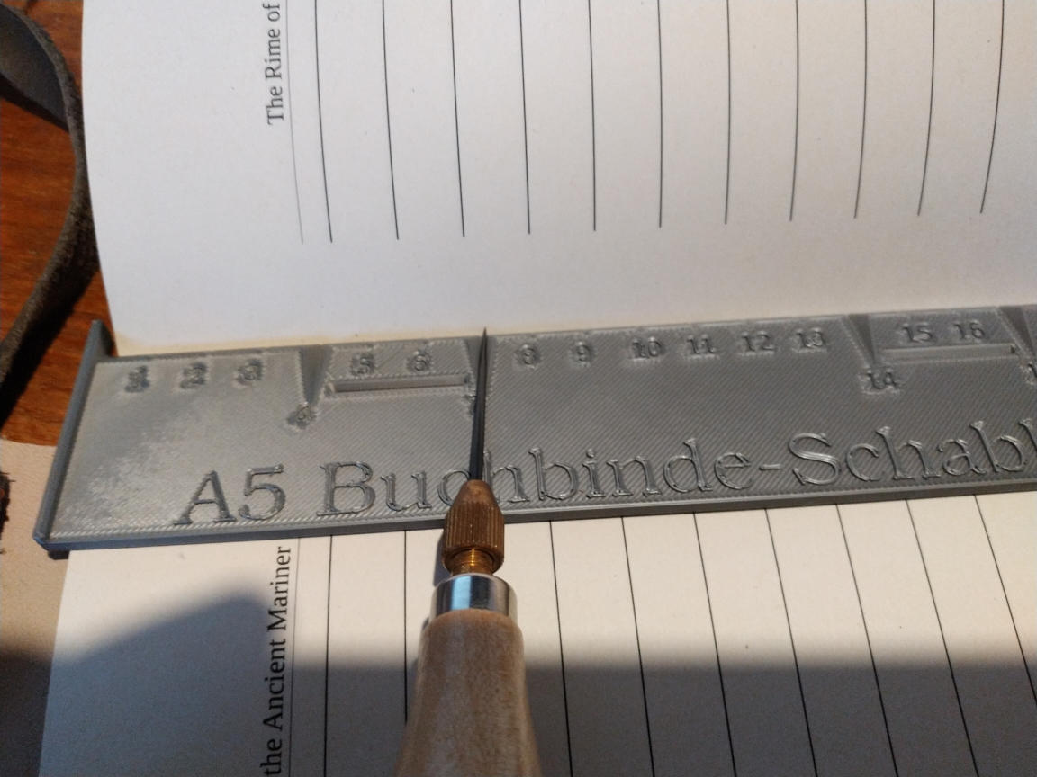
As you can see in the photo - you simply use the large grooves to point your awl to the right spot. The left edge is elongated, so that you can bunch the paper of the signature against it for easy alignment.
The base design is a relatively simple OpenSCAD design. If you need to adjust to a different paper format or imperial markings read the description below for some hints.
If you simply want to print it, download the model here:
The print takes about 40 minutes on my Prusa printer. This is mainly due to the large surface area, it doesn't actually use that much volume (ca. 21g of PLA, 17.5cm3).
If you want to modify the design, read on.
I'm assuming that you are familiar with the OpenSCAD script language - there are plenty of tutorials and good documentation out there. The measurements in the script are in millimeters - which is the default for STL export.
The script is commented to give you a chance to parse it. It starts with two functions that help aligning the cm marks on the ruler - they return corrected positions for the lettering. You may need to change these functions if you alter the font. The cm_x function needs to be changed if you change the needle slots - it returns different positions for those slots, since they intrude farther into the ruler body.
The actual ruler is contained in the large union. The first cube gives you the size of the ruler main body - if you need a longer ruler you need to change this as well as the "edge" cube that subtracts the front slope.
The needle slots are also in that first difference block - if you want to change their position you will have to adjust not just their position (the y part of their translate), but also the "thread hints" below and probably the cm_x function to adjust numbers.
The "name of the thing" section generates the large title lettering on the ruler - if you don't like German, feel free to change the string.
The last block contains a for look that generates the cm marks on the ruler. The array has the format [start:step:end], meaning the default of [10:10:210] will generate the first mark at 10mm, then one every 10mm, and the last one at 210mm. The numbers are generated by the text statement - adjust the formula if you don't like centimeters.
One nifty trick in OpenSCAD is to prefix a statement with "#" - this makes is visible in translucent pink - even if it is a negative volume. This can be used to debug the effect of changes by highlighting where your change ends up. If you prefix with "*" the feature disappears.